
SIP, RTP, and the Static IP Problem on AWS Fargate
Back After a While
It has been a couple of years since I last wrote here. Life got busy in the best possible way — a role change, a lot of new territory to learn, and the usual chaos of family life. The blog quietly fell off the list.
What is pulling me back is that I have been working on some genuinely interesting infrastructure problems. The kind where you think the answer is obvious, try the obvious thing, and then spend a few days figuring out why it does not work. Those are the problems worth writing about.
So here we go.
What the Service Does
Before getting into the networking problem, it helps to understand what the service actually does — because the problem only makes sense in that context.
The service runs inside an ECS Fargate container on AWS. When triggered, it places an outbound phone call over SIP to an IVR system. Once the call connects, it listens to the audio coming back, transcribes it in real time using a speech-to-text service, feeds the transcript to a large language model to decide what to say next, converts that response to speech using a text-to-speech service, and plays it back into the call. It is essentially an AI agent that can navigate a phone system autonomously.
The call flow looks like this:
  ┌──────────────────────────────────────────────┐
  │  ECS Fargate Container                        │
  │                                               │
  │  1. Send SIP INVITE  ──────────────────────►  │  IVR / Phone System
  │  2. Receive SDP answer                        │
  │  3. Receive inbound RTP audio  ◄────────────  │
  │  4. Transcribe audio (speech-to-text)         │
  │  5. Send transcript to LLM                    │
  │  6. Get response text from LLM                │
  │  7. Convert response to speech (TTS)          │
  │  8. Send outbound RTP audio  ──────────────►  │
  └──────────────────────────────────────────────┘
Steps 4 through 7 happen in near real time, inside the same call. The container is both a SIP client and a media endpoint.
The service connects to many separate external phone systems — each one independently configured and each one with its own firewall. That is where the problem starts.
How SIP and RTP Work Together
SIP is the signalling protocol. It sets up, modifies, and tears down calls. RTP is the media protocol — it carries the actual audio, as a stream of UDP packets.
When the container places a call, it sends a SIP INVITE. Inside that INVITE is an SDP (Session Description Protocol) body that tells the remote side two things: what IP address to send audio to, and what port to use.
The relevant SDP lines look like this:
c=IN IP4 <container-ip>
m=audio <port> RTP/AVP 0
The c= line is the connection address. The m= line is the media line — it names the port and the codec (0 is PCMU, standard G.711 audio at 64 kbps).
The remote side reads those two values and starts sending RTP audio packets to that IP and port. It does not negotiate further. It does not check whether the IP matches where the SIP signalling came from. It just sends audio to whatever the SDP says.
This is the crux of the problem. The container needs to advertise a real, reachable, stable IP in that c= line. And that IP needs to accept inbound UDP on the advertised port.
The Problem
The container runs in a private subnet. It has no public IP of its own. Outbound traffic goes through a NAT Gateway, which does have a static Elastic IP — so outbound SIP signalling has a stable source address. That part is fine.
The problem is inbound RTP. The remote phone system will send audio to whatever IP the container put in the SDP c= line. That IP needs to be:
- Publicly reachable from the internet
- Static — it cannot change between deploys or task restarts
- Able to forward UDP to the container on the exact port advertised
The container connects to many external systems, each with its own IP allowlist. Those allowlists are configured once at onboarding. If the IP changes, every one of those systems needs to be updated. That is not a realistic operational model.
So the requirement is:
The container must always advertise the same IP in the SDP
c=line, and inbound UDP must reach it on the exact port advertised — across every deploy, restart, and crash recovery.
Why the Obvious Approaches Do Not Work
Just give the container a public IP
ECS Fargate lets you set AssignPublicIp: ENABLED. The container gets a public IP. Put that in the SDP c= line. Done?
Not quite. That IP is dynamic. Every time the task is replaced — deploy, crash, spot reclaim — it gets a new one. Every external system would need to update its allowlist. Not workable.
Attach an Elastic IP directly to the Fargate ENI
An Elastic IP (EIP) is a static IP you own in AWS. You can attach it to an EC2 instance and it stays put. Surely you can do the same for a Fargate task?
No. Fargate ENIs are marked RequesterManaged: true — they are owned by the AWS Fargate service account, not yours. When you call AssociateAddress to attach an EIP, AWS returns AuthFailure. This is a platform constraint, not an IAM permissions issue. There is no workaround.
Let the NAT Gateway handle inbound RTP
The NAT Gateway EIP is static. The container’s outbound SIP already uses it. Can the same IP handle inbound RTP?
Here is where UDP breaks down. A NAT Gateway rewrites the source port on every outbound UDP packet. It only lets return traffic back on that exact rewritten port. But the remote phone system is not sending return traffic — it is initiating its own inbound UDP stream to the port the container advertised in the SDP.
1. Container binds RTP socket on port 16384
2. Container sends SIP INVITE with c=<NAT-EIP> m=audio 16384
3. Container sends RTP keepalive → NAT rewrites source to NAT-EIP:RANDOM_PORT
4. Remote system sends inbound RTP to NAT-EIP:16384 (from the SDP)
5. NAT has a flow for :RANDOM_PORT, not :16384 → drops the packet
6. Container receives zero audio frames
Everything looks fine from the signalling side. The call is established. But framesRx stays at zero. The NAT Gateway is not the right tool for inbound UDP where the port is fixed by the SDP.
| Approach | Why it fails |
|---|---|
| Dynamic public IP on Fargate | Changes on every task replacement |
| EIP directly on Fargate ENI | Platform blocks it — requester-managed ENI |
| NAT Gateway for inbound RTP | Port rewriting breaks inbound flows |
What Actually Works — NLB with a Static EIP
A Network Load Balancer (NLB) operates at Layer 4. Unlike a NAT, it does not rewrite ports — it forwards UDP packets with the destination port intact. And you can assign a static EIP to an NLB. That EIP is yours, it does not change, and it survives every task replacement.
The container puts the NLB EIP in the SDP c= line. The remote system sends inbound RTP to that IP on the advertised port. The NLB forwards it straight to the container on the same port. No rewriting. No dropped packets.
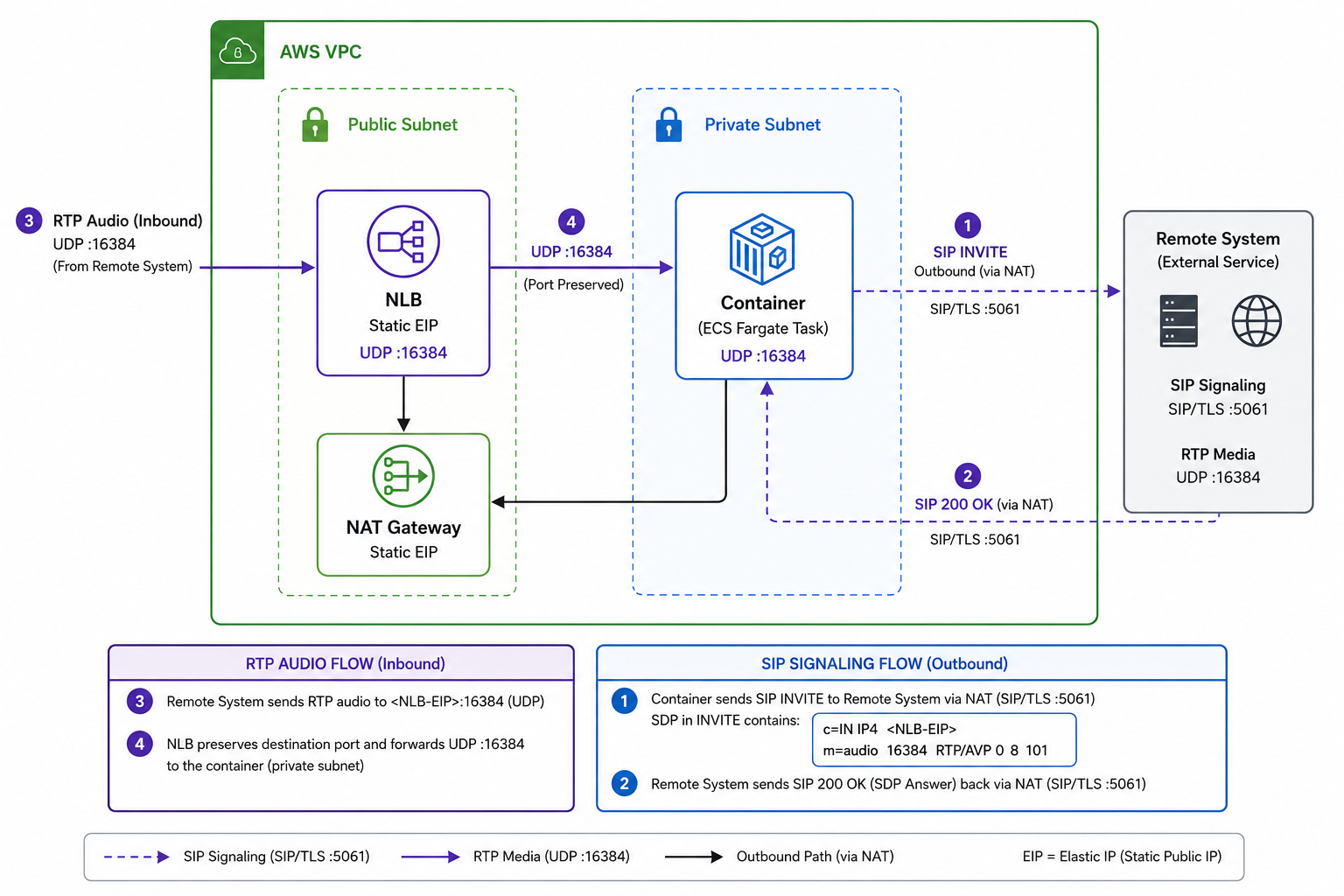
Outbound SIP goes through the NAT Gateway — that EIP is also static and is what the remote system sees as the SIP source address. Inbound RTP comes in through the NLB EIP. Two separate paths, both with stable IPs. The asymmetric routing is fine — the remote system honours the SDP address for inbound audio regardless of where the SIP signalling came from.
This was confirmed on a live call. The container received over 4000 audio frames through the NLB, the AI agent completed its task, and the call ended cleanly.
The SDP Connection — Where the IPs Come From
The container has two environment variables that drive the SDP:
ADVERTISED_PUBLIC_IP— the NLB EIP, injected at deploy time. This goes into thec=line.RTP_PORT(or a pool port, once concurrency is added) — the port the container binds its UDP socket to. This goes into them=line.
The SDP the container sends in the INVITE looks like:
c=IN IP4 <NLB-EIP>
m=audio 16384 RTP/AVP 0
a=rtpmap:0 PCMU/8000
The remote system reads this, sends audio to <NLB-EIP>:16384, the NLB forwards it to the container’s private IP on port 16384, and the container’s bound UDP socket receives it.
The three values that must match exactly:
NLB listener port == container UDP bind port == SDP m= port
If any of these drift — say the container binds on 16385 but the NLB listener is on 16384 — inbound audio is silently dropped. The call is established, the NLB target shows healthy, but framesRx is zero. This is the most confusing failure mode in the whole setup. The fix is to drive all three from a single environment variable and never configure them independently.
Concurrency — One Port Per Call
One NLB UDP listener maps to one port. One port handles one concurrent call. For five concurrent calls you need five listeners, five target groups, and five ports.
AWS caps NLB listeners at 50 per load balancer. That is a hard limit. So one NLB gives a ceiling of 50 concurrent calls.
There is a second constraint: ECS native load balancer integration only supports up to 5 target groups per service. With an ALB already using one slot, there are only 4 left — not enough for a meaningful port pool. So the container handles its own registration.
On boot, the container reads its private IP from the ECS task metadata endpoint and calls the ELB API to register itself into all the RTP target groups at once. On shutdown it deregisters.
// on boot — register this task's private IP into every RTP target group
const ip = await getTaskPrivateIp();  // from ECS metadata
for (const [port, tgArn] of portToTgArn.entries()) {
  await elbv2.registerTargets({
    TargetGroupArn: tgArn,
    Targets: [{ Id: ip, Port: port }]
  });
}

// on SIGTERM — clean up before the task stops
process.on('SIGTERM', async () => {
  await rtpPool.deregister();
});
Per call, the pool allocator picks a free port, binds the UDP socket, and puts that port in the SDP. When the call ends, the port goes back into the pool.
One finding from testing: RTCP (the companion control stream to RTP) is not required. The remote system did not mandate it, and the live call was clean without it. This matters because it means each call uses one port instead of two — keeping the ceiling at 50 rather than 25.
Scaling Beyond 50
Growing from 5 to 50 concurrent calls is free and invisible to external systems — same NLB EIP, just more listeners and target groups on the same load balancer. No allowlist changes needed anywhere.
Going beyond 50 means adding another NLB with its own EIP. That new EIP has to be whitelisted by every external system. That is the expensive, coordinated step.
The scaling path in order:
- Grow the port pool from 5 to 50 — free, no external changes
- Size the container up vertically — more CPU and memory handles more concurrent calls on the same task. This is the real capacity lever before the port ceiling matters.
- Add more NLB and EIP units when genuinely past 50 concurrent — requires external systems to update their allowlists
For a service connecting to a large number of external systems, the cleanest long-term answer is BYOIP — bring your own IP block, publish it as a single CIDR that everyone whitelists once, and assign NLB IPs from it. Future capacity growth never touches anyone’s allowlist. That is the target state for real scale.
Twitter Facebook LinkedIn
Comments